

Steam turbine controls consist of two linked control systems, the Governor and the Valve Operators. The Governor is a specialized closed loop controller which maintains an adjustable set point speed or load on the turbine. The Valve Operator accepts the Governor's output demand and close a position loop for steam admission valve as commanded by the Governor. When tasked with the replacement of an old or unreliable system, several key issues need examination before selecting any of the multitude of retrofit options. This Quick Notes will review alternate steam turbine control options and provide links to LCC recommendations.
Electric actuators are ideal steam turbine governor valve positioners, but care must be taken in specification to avoid pitfalls. Unless accompanied by independent rapid trip closure devices, electric actuators should not be used on steam turbine stop valve applications. This Quick Note addresses the key Electric Actuator specification issues and respective LCC links for solutions.
Almost without modern rival, steam and gas turbine vibration monitoring systems are notoriously misapplied. Most systems neither warn operators of pending disasters nor contribute much in the way machinery condition knowledge. The culprit error in most systems is the use of anti-friction (ball, roller) bearing technology on journal (sleeve or tilting pad) bearing machines coupled with a misunderstanding of turbine rotor dynamics. With respect to vibration characteristics, turbines do not behave at all like electric motors which are the design target for all popular vibration monitoring systems. Important specification issues are:
Since most turbine supervisory vibration monitors do not accurately detect true rotor deflection (The LCC ALERT System is the exception), temporary instrumentation is necessary to determine the need for balancing. Temporary sensors and analyzers should always be scheduled following repair work on turbine rotors which affects the rotor mass balance like blade and shroud repairs or replacements. Likewise, the following preparatory tasks are recommended:
The days of relying upon centrifugal bolts to mechanically trip turbines on repeated over speed test runs are over. Over speed testing of trip bolts has been the number one turbine failure condition, and it makes no sense to stress the blades when unnecessary. There are, however, several key points to consider in specifying a digital over speed protection system:
Projects to modernize steam turbine controls have a natural progression of tasks which need timely completion to enable a desired completion in time for an outage installation. We are often asked what lead times are for "typical" system orders. Although there really is no "typical" order, this Quick Notes presents a task time estimate which is good for planning.
New EPA regulations needed to prevent contamination of waterways have redefined design requirements of both hydro and steam turbine control systems. Previous practices of specifying high pressure hydraulic valve operators from central oil skid systems are now obsolete in light of increased costs to secure systems against hydraulic leaks.
At some point in the course of an electric actuator upgrade for steam turbine valves the question of secure mounting and proper bolt sizing of the actuator mounting usually arises. In these instances a common misconception of bolted flanges often surfaces. This quick note discusses the correct bolt stress analysis technique for an actuator mounting flange operating under tensile load.
Governor valve closure rates are often a major point of discussion when planning electric actuator upgrades. It is important to understand the design criteria for governor valve closures before expending large sums for excess closing speed control.
Digital Redundant Overspeed Trip upgrades replacing mechanical "bolt, spring, and lever" OEM turbine overspeed trip hardware provide many advantages and can reap quick paybacks. There are pitfalls, however, and care must be taken in specifying a sound replacement.
Some new instrumentation technology helps solve an old problem of leveling steam chest governor valve lift bars. For a very modest tool investment both good results and repeatable settings can be achieved.
Generation steam turbines in the US will likely be subject to proving frequency control readiness in the future as NERC (National Energy Reliability Council) advances toward European standards in governor testing. Properly functioning turbine governors are the number one asset in fighting grid frequency upsets, but proving their efficacy involves some special governor features. Having supplied systems for the UK's National Grid, where on line testing has been required since 1995, LCC is familiar with these features and the testing process.
HP Governor Valves on most Main Feed Pump Turbines are rigidly coupled to operators over fulcrum linkages. In calibrating valve stroke the closed valve or minimum operator position must be determined, however, the absolute position changes significantly with the thermal expansion growth of the valve stem in the steam flow. If set for contact while "hot" the valve will leak through at this position when cold. If set for contact when "cold" the valve will be over-driven with high closing force if closed when hot which can distort linkages and damage the valve seat.
Unlike their mechanical-hydraulic ancestors, digital turbine governors can respond to speed excursions to prevent excess over-speed in instances of sudden load disconnect from unmonitored causes (like transformer failures or off-plant disconnects). While the ensuing excursion is typically defended by over speed trip devices closing stop valves, a governor intervention can reduce the excursion speed, but it takes a fast digital governor to be of value. Many turbine governors are not. This Quick Note arms the engineer with the calculations to find out what's needed in minimum response for effective speed limiting.
Turbine oil flushes have become rare. Although one of the best preventative maintenance procedures that can be implemented, they are often victims of a shortage of maintenance time and thought of as too messy. An oil flush cannot be performed at a computer keyboard, and therefore loses popularity. With careful planning and the right equipment on site a successful flush can save the turbine from major contamination issues, removing internal piping, hydraulic relay bores, and internal oil passages of contaminants otherwise ready to foul trip systems, wipe bearings, and seize control devices.
Turbine governor systems have historically been controllers and not instrument information systems. With the availability of plant Distributed Control Systems (DCS) data from multiple plant control systems can be presented on workstations, control managed by soft buttons, and data displayed in both real time and historical trend formats. Some governors have also evolved to provide DCS-like features and capabilities. The specifiers of a modernization retrofit must take care not to duplicate expensive hardware and distributed capabilities for plants already operating full featured DCS.
An Effective Means to Mitigate Fukushima-Type Event SBO
Why use a Governor at all? Why not have the plant Distributed Control System (DCS) handle the turbine speed or load control? These are not trivial questions. In some cases a DCS can perform quite satisfactorily as a steam turbine governor. A good guideline for determining when a DCS can handle a turbine control task is to compare the required application response time with the DCS functional response time. If a DCS is too slow to enact control changes to avoid upsets, it probably needs external help to close the turbine speed control loop. The application response time for turbine control is determined by calculating one-fifth the maximum acceleration rate of the turbine (RPM/second) which provides either a process upset or an over speed trip, whichever is less. For example, a typical feed pump turbine has a maximum acceleration rate of 1000 RRM/second and operates within 500 RPM of over speed trip. For over speed control, an adequate DCS response period is then 500/1000 x 1/5 = 0.1 second. Many newer DCS platforms have I/O scan cycles this quick. The process upset is next evaluated. A BFPT feeding a drum-type boiler has a very forgiving 1000 RPM upset delta, yielding a needed control response period of 1000/1000 a 1/5 = 0.2 second which can also be handled by a DCS. The same BFPT in a once-through boiler or nuclear RFPT application has a process upset of 100 RPM yielding a response period of 100/1000 x 1/5 = 0.02 seconds which disqualifies all DCS from successfully controlling the loop. For reference, LCC 200-Series and Series-2 Governors have loop closures of 15 milliseconds. In summary, the DCS can do some things but not ALL things.
Governor Valve Operators were mechanical/hydraulic monsters in the old days and high pressure hydraulics in the later 1900's, but since the turn of the century roller screw electric actuators are by far the preferred type for a host of reasons:
Electric actuators are ideal steam turbine governor valve positioners, but care must be taken in specification to avoid pitfalls. Unless accompanied by independent rapid trip closure devices, electric actuators should not be used on steam turbine stop valve applications. This Quick Note addresses the key Electric Actuator specification issues and respective LCC links for solutions.
Almost without modern rival, steam and gas turbine vibration monitoring systems are notoriously misapplied. Most systems neither warn operators of pending disasters nor contribute much in the way machinery condition knowledge. The culprit error in most systems is the use of anti-friction (ball, roller) bearing technology on journal (sleeve or tilting pad) bearing machines coupled with a misunderstanding of turbine rotor dynamics. With respect to vibration characteristics, turbines do not behave at all like electric motors which are the design target for all popular vibration monitoring systems. Important specification issues are:
Since most turbine supervisory vibration monitors do not accurately detect true rotor deflection (The LCC ALERT System is the exception), temporary instrumentation is necessary to determine the need for balancing. Temporary sensors and analyzers should always be scheduled following repair work on turbine rotors which affects the rotor mass balance like blade and shroud repairs or replacements. Likewise, the following preparatory tasks are recommended:
The days of relying upon centrifugal bolts to mechanically trip turbines on repeated over speed test runs are over. Over speed testing of trip bolts has been the number one turbine failure condition, and it makes no sense to stress the blades when unnecessary. There are, however, several key points to consider in specifying a digital over speed protection system:
Projects to modernize steam turbine controls have a natural progression of tasks which need timely completion to enable a desired completion in time for an outage installation. We are often asked what lead times are for "typical" system orders. Although there really is no "typical" order, this Quick Notes presents a task time estimate which is good for planning.
ELAPSED TIME: 3 MONTHS
ELAPSED TIME: 5 MONTHS
ELAPSED TIME: 6 MONTHS
ELAPSED TIME: 7 MONTHS
ELAPSED TIME: 8 MONTHS
ELAPSED TIME: 14 MONTHS
ELAPSED TIME: 15 MONTHS
ELAPSED TIME: 15-1/2 MONTHS
Given the task progression above, a major turbine controls project can be installed sixteen (16) months from conception and ten (10) months from contract award.
New EPA regulations needed to prevent contamination of waterways have redefined design requirements of both hydro and steam turbine control systems. Previous practices of specifying high pressure hydraulic valve operators from central oil skid systems are now obsolete in light of increased costs to secure systems against hydraulic leaks.
When the EPA instituted Spill Prevention and Control Plans requirements it was not at first apparent that point source control was included in systems subject to fluid release. When clarified, new focus in SPCC emphasizes prevention of not only release of oils and synthetic fluids into waterways, but adds engineering control of point sources. This can be visualized as a two-level defense plan. The last resort defense is a waterway discharge monitoring and diversion system which allows treatment processes to be applied prior to public release when plant contaminants have entered plant drain systems. The first level defense is preventing the various system discharges in the first place into the plant drain systems.
While older pre-1970s turbine hydraulic controls designed by turbine OEMs observed the practice of Guarded Oil Piping, in which all externally run pressurized lines are surrounded by drain return lines with gravitational paths to reservoirs, newer and retrofit hydraulics did NOT. The reason for not following guarded oil piping practices with Fyrquel hydraulic delivery systems was justified at the time because Fyrquel is not flammable and therefore potential leaks would not produce fire hazards as they would with the flammable turbine lube oil based systems. With the need for SPCC this excuse has vanished and served Fyrquel-based systems users with a major problem... how to retrofit guarded piping, hundreds of feet of it, suspended about the turbine floor.
Since each high pressure synthetic fluid operated valve will have a minimum of three stainless steel lines run from the central hydraulics skid to the valve (high pressure, return, and trip header), some measure of leak control will be needed. If there is any question as to whether these high pressure systems ever leak and whether they qualify as sources requiring point source control, a stroll down a steam turbine floor will evidence the paint damage to turbine lagging below each EHC operated valve. While the assertion can be made that leaks are rare, this in itself is no excuse for not complying to point source control.
The task and expense of implementing point source engineering controls is considerable. Each three-pipe run to each valve will require a guarded protection pipe with leakage monitoring and managed return to qualified vessels.
A simpler solution than attempting to guard high pressure EHC piping is to abandon the piping and related valve operators in entirety. With no oil lines there is nothing to guard. Replacement operators in the form of electric actuators for governor and interceptor valves and self-contained hydraulic operators with internal leakage monitoring for stop, throttle, and reheat stop, and bypass valves will not only solve the SPCC problem but also improve turbine control with a state-of-the-art valve control system.
At some point in the course of an electric actuator upgrade for steam turbine valves the question of secure mounting and proper bolt sizing of the actuator mounting usually arises. In these instances a common misconception of bolted flanges often surfaces. This quick note discusses the correct bolt stress analysis technique for an actuator mounting flange operating under tensile load.
Referring to the figure below, when calculating the required bolting of a flange to be subjected to a tension force "F", the sum of the flange bolt stress under prescribed torque for the bolts should provide a healthy safety factor above "F". The misconception that often is suffered in reviewing the selection is the erroneous tendency to then recalculate the stress of the bolting as the torqued stretch PLUS the distribution load of "F". This stems from viewing the bolt clamping force and the load as aligned rather than opposed.
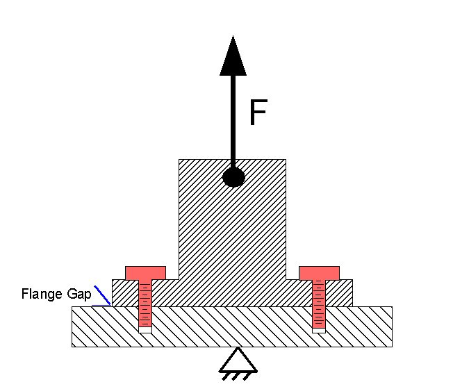
In fact, the applied load "F" causes NO ADDITIONAL bolt stress as long as the flange gap remains zero. Think of this in light of the bolts cannot be additionally stretched without relative motion between the flange and base. Of course, no gap can occur as long as the clamping force exceeds the load.
The failure to properly understand the flange forces in this type of case can result in oversized and under-stressed flange bolting which reduces friction clamping between the surfaces which can lead to bending moments, slippage, and fatigue.
Although seemingly a basic mechanical engineering analysis, this has been improperly reviewed in enough cases to cause alarm.
Governor valve closure rates are often a major point of discussion when planning electric actuator upgrades. It is important to understand the design criteria for governor valve closures before expending large sums for excess closing speed control.
In redundant steam feed mechanical drive turbines each steam supply source (HP main steam and LP reheat steam for Westinghouse and GE feedwater pump turbines) must have Stop Valve Operators capable of closing steam supply to the turbine within sufficient time to arrest speed excursions to less than 12% under rated operating conditions, or typically one second. Further, Governor Valve Operators are to close following the Stop Valve trip to prevent a reset run-off situation. No performance standard is assigned Governor Valve Operator closure rate, but it is generally accepted that positive predictable closures are better to assist in emergency shut down situations. Also, both the Stop Valve Operators and the Governor Valve Operators are supposed to have full closure under input positioning signal loss failure mode. These criteria are a homogilation of ASME Power Test Code and industry insurance underwriter's requirements established in the 1950's. European standards vary, and are exempt from this discussion.
The question addressed by this paper is how an electric actuator retrofit compares in meeting the trip performance of the Governor Valve Operators with the original equipment servomotor (Westinghouse) and secondary operating cylinder (GE) operators.
Feed pump turbines are mechanical drive prime movers which operate at speeds using one of two steam supplies. In normal operation, the available enthalpy of the throttled steam supply in service equals the retarding torque of the driven pump when controlled to a steady state speed by a governor. Unlike a generation turbine, the retarding torque load is only suddenly lost in a catastrophic failure incident like a coupling bolt shear failure or pump discharge line failure. A generation turbine can lose all load by a main disconnect breaker opening and is therefore treated as an entirely different case. For the purposes of failure analysis the feed pump turbine load loss is considered an extremely rare asynchronous event.
Original hydraulic Governor Valve Operators connect to trip oil headers via check valves and close position upon hydraulic trip (autostop) oil pressure loss. Hydraulic Governor Valve Operator closure times vary between 1.5 and 2.5 seconds.
Electric Governor Valve Operators connect to electrical trip and trip oil header pressure switches and close position upon hydraulic trip (autostop) oil pressure loss. Electric Governor Valve Operator closure times are 0.4 to 0.7 seconds.
Original hydraulic Governor Valve Operators have the following possible failure scenarios and closure affects:
Of these potential failures, a catastrophic turbine failure can only occur in the instances of the last two cases if combined with a simultaneous combination of pump mechanical load loss and Stop Valve Operator failure.
Electric actuator Governor Valve Operators have the following possible failure scenarios and closure affects:
Of these potential failures, a catastrophic turbine failure can only occur in the instance of the last case if combined with a simultaneous combination of pump mechanical load loss and Stop Valve Operator failure. Thus three asynchronous events are required.
Electric actuator replacements of hydraulic operated governor valves improve trip response in normal operation and reduce potential catastrophic failure potential in the cases of rare simultaneous asynchronous events.
Digital Redundant Overspeed Trip upgrades replacing mechanical "bolt, spring, and lever" OEM turbine overspeed trip hardware provide many advantages and can reap quick paybacks. There are pitfalls, however, and care must be taken in specifying a sound replacement.
Most smaller mechanical drive steam turbines were designed with centrifugal operating mechanical overspeed trip mechanisms which when properly functioning moved levers to dump hydraulic valves on turbine autostop oil headers thus initiating a trip when the rotational speed reached the safety limit. Unfortunately problems like oil contamination, bent levers, hammered strike pins, and looseness can cause these devices to fail.
A further disadvantage of the mechanical bolt systems is that the turbine needs to be physically brought to the overspeed trip speed to test or confirm the setpoint. For years the very act of testing mechanical overspeed trip devices has been the number one cause of turbine failures.
A three channel system with 2-of-3 voting/auctioning with each channel having an independent speed probe and monitor will nicely supply the one RPM detection accuracy and 15 millisecond response time needed for turbine overspeed trip. Advantages of upgrading to electronic trip are:
3.1 Timing Wheels... If the turbine does not have a square-cut toothed timing wheel it is far better to install one than to use an existing spur gear as a speed target. Spur and power gears produce distorted speed pulse profiles which can become marginal in some situations. Also, the width of the timing wheel needs to account the total thrust travel of the turbine so that routine thrust positioning does not miss-target probes.
3.2 Speed Probes... If Zero Speed Detection Monitoring is to be included, the speed probes must be active style (rather than magnetic) in order to detect down to slow speed tooth pass speeds. Active probes also benefit overspeed systems by having fault detection at any speed, not just 200 RPM+.
3.3 Timing Gear Mounting... Care must be taken to securely mount timing gears to the turbine rotor. Turbine stub shafts should be avoided due to coupling failures potentially eliminating all speed channels at once.
3.4 Speed Probe Mounting... Probes must be securely mounted in accurate alignment to target toothed timing wheels. Probe brackets must not resonate with operating turbine speeds. Provision should be made to simplify probe gapping, even while the turbine is spinning.
3.5 Active Probe Transmitters... When using active speed probes, each should have a corresponding transmitter when wiring runs are greater than 25 ft. to the monitors. Amplified signals should be RS-422 or RS-485.
3.6 Test Signal Injection... Although dropping the test speed is accepted by insurance carriers, many then want to see the individual speed channels each verified as initiating at the full overspeed setpoint, thus "closing the loop" on calibrations. A Test Signal Injection capability is needed to meet this criteria which connects simulated speed signals from a built-in square wave generator to the channel in test only with isolated trip output. Without this feature a cumbersome method of attaching an external signal generator and manual disconnections is needed.
3.7 Zero Speed Engagement Delay... The Zero Speed Monitor circuits should have a built-in adjustable engagement delay period to allow the turning gear (Bendix device) a second or two to come to speed and engage the turning gear pinion on the bull gear. Without this delay feature the initial speed sensing will drop out the engagement immediately and prevent turning gear operation.
3.8 High Speed Alarm... A good feature is an additional speed setpoint programmed as a High Speed Alarm. This is used as a warning to operators when the turbine speed is approaching the overspeed setpoint and can often prevent an accidental speed excursion and turbine shutdown.
Please follow the links to view specific LCC solutions in overspeed and zero speed redundant digital monitors.
Model 470 Digital Speed Monitor.Some new instrumentation technology helps solve an old problem of leveling steam chest governor valve lift bars. For a very modest tool investment both good results and repeatable settings can be achieved.
A row of sequential lift poppet valves which are raised off their seats by a common lift bar by two lift rods (Fig. 1) is a common governor valve steam chest design which has been used by many manufacturers. By setting increasing lift clearances between the valve stem nuts and the lift bar a relatively linear progression of steam admission is theoretically possible. One assumption, that the lift bar is level, has traditionally been difficult to confirm short of proof in operation with nozzle port pressure measurements. If the lift bar is not level the steam admission rate with stroke will be accelerated at valve lift points and proper control can be compromised.
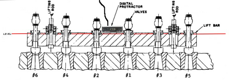
This Quick Note illustrates an easy way to adjust and confirm a level bar using a digital protractor with an RS232 output cable to a laptop for remote display.
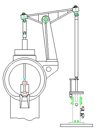
Figure 1, Fulcrum-Lift rack Side View (of course with an electric actuator... this is on the LCC site!)
With the steam chest cover off, install a digital protractor with RS-232 output on the lift bar at center, then run the cable out the cover flange. Place a set of at least four level blocks of 0.500-inch thickness (or precision bolt spacers) on the flange at each side so as to allow the digital protractor cable egress to a laptop. Now set the cover and secure the flange bolts, maintaining the cover alignment, albeit slightly raised. The lift rod/s may now be adjusted for a perfectly level lift bar as read on the digital protractor program readout on the laptop.
Generation steam turbines in the US will likely be subject to proving frequency control readiness in the future as NERC (National Energy Reliability Council) advances toward European standards in governor testing. Properly functioning turbine governors are the number one asset in fighting grid frequency upsets, but proving their efficacy involves some special governor features. Having supplied systems for the UK's National Grid, where on line testing has been required since 1995, LCC is familiar with these features and the testing process.
All generation steam turbines with the exception of thermally limited nuclear plant units are expected to serve in a grid stability function at an assigned regulation rate. This can be thought of as proportional frequency control. Prior to synchronization, turbine governors work as speed controllers. Once synchronized, turbine governors as supposed to work as proportional frequency controllers, but proper operation is very difficult to prove and many older steam turbine governor systems have little, if any, practical frequency control to contribute to the grid. Although load control centers may switch tie lines, start peakers, and ramp load setpoints of units under their control, these operations take on the order of minutes to execute. A governor frequency correction on the other hand can be performed in seconds. This is why NERC has an interest in maximizing operative governors on the grid.
In 2002 some innovative engineers at load control centers came up with a means of determining a particular generation unit's lack of governor frequency response by observing the unit net electrical output immediately following a large system frequency upset. The engineers noticed that some units performed as expected, i.e., if the grid frequency dropped suddenly, the net electrical output of the unit's generator immediately increased according to the assigned regulation. Many units were also observed to "deadline" through disturbances, providing no corrective actions whatsoever. Figure 1 illustrates correct and non-compliant unit governor responses. These findings led to the issuance of corrective action letters to the non-compliant unit operators.
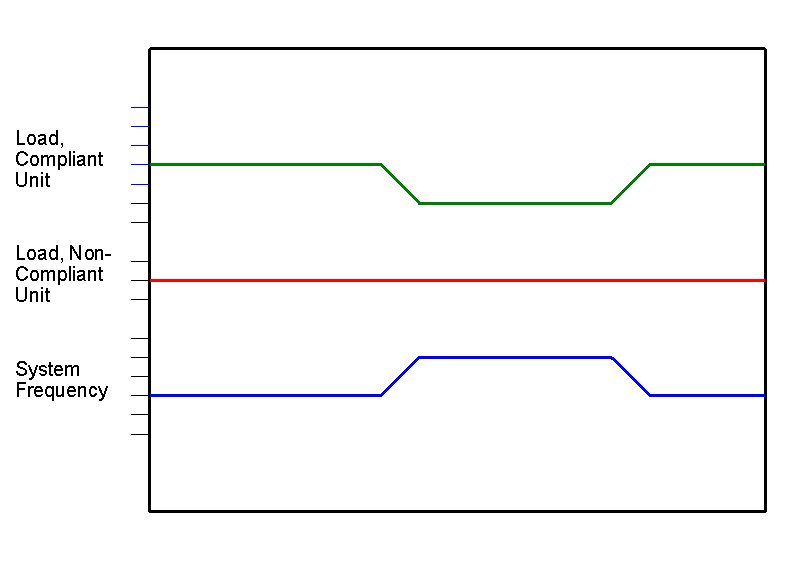
Figure 1
In 2007 after major blackouts, the focus turned to means of proving governor functionality on a routine basis as has been the case in the UK. NERC issued PRC-018 to address the requirement (www.nerc.com/files/PRC-018-1.pdf). Under PRC-018 testing proof must be supplied upon NERC demand. While the "deadline response" to grid frequency upsets identifies obviously inoperative governors, the new testing standards go the step further to prove that the governors are regulating to the percentage required and stand ready to respond to grid upsets. Some power operator associations have resisted this testing, falsely claiming that technology does not exist currently to support the program. One needs only to look at the now sixteen years of testing in the UK to debunk this excuse. LCC's Series 2 Euro Governors have had the capability since 2005.
With the experience of designing and installing steam turbine governors for generation units on the UK grid which are mandated to include built-in on line regulation testing, LCC has implemented the methods and instrumentation required. The basic method of test is to introduce a variable level offset summed to the real time governor speed feedback as received from electronic speed probes. This pretty much eliminates older mechanical-hydraulic governor systems from compliance which do not utilize electronic speed feedback, but for many additional reasons these systems should be replaced at once.
The offset magnitude to be summed is established by a external voltage -10 vdc to +10 vdc steering signal such that the full range of required frequency response may be tested. Safety interlock mechanisms prevent accidental test injection during normal operation. With this type of system the governor regulation efficacy can be proven under any pre-existing operating conditions with a reasonable load ceiling (not operating at or close to 100% load). By recording net load changes with both positive and negative frequency offsets the true regulation of the turbine governor is established. In some instances the testing will uncover lower or higher regulation rates than designed or specified. In these cases the testing program provides a calibration adjustment to bring the governors into correct operation.
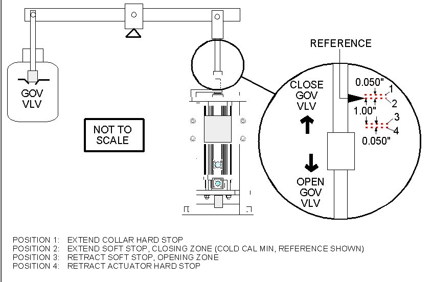
HP Governor Valves on most Main Feed Pump Turbines are rigidly coupled to operators over fulcrum linkages. In calibrating valve stroke the closed valve or minimum operator position must be determined, however, the absolute position changes significantly with the thermal expansion growth of the valve stem in the steam flow. If set for contact while "hot" the valve will leak through at this position when cold. If set for contact when "cold" the valve will be over-driven with high closing force if closed when hot which can distort linkages and damage the valve seat.
Original equipment HP Governor Valve operators, or Servomotors, have been a source of maintenance trouble for years with the primary difficulty centering around returning a Servomotor to factory design stroke of minimum and maximum positions over control signal range. The valve thermal growth is often ignored in calibration attempts, but shouldn't be.
The full effective stroke of these valves is usually not long, falling in the 0.625-inch to 1.0-inch range. Even a small error in seating position can result in a significant steam flow which will be uncontrolled by any governor or upstream system. Likewise, distorted linkage arms and pivot pin holes are routinely detected in outage inspection efforts indicative of excess closing force.
Several users have found they needed to replace entire linkage arms to repeat stroke ranges after suffering over-travel damage.
Replacing the servomotor with an electric actuator configured with a Closing Zone feature eliminates the thermal offset linkage stress and steam pass problems permanently and relieves maintenance personnel from a difficult compromising calibration. With the controlling Servo Drive implementing a special control algorithm that treats the last 2% of travel as a Closing Zone, both positive valve closure and low linkage closing loads are achieved. Within the Closing Zone position commands to decrease the valve position are processed with a fixed current drive value to the actuator motor, applying enough force to seat the valve at whatever stage of thermal growth it might be in. Similarly, a Opening Zone prevents excess opening travel stress. The advanced tuning capabilities of the servo drive operated electric actuator permit this level of sophistication which is impossible with cruder hydraulic operators.
Unlike their mechanical-hydraulic ancestors, digital turbine governors can respond to speed excursions to prevent excess over-speed in instances of sudden load disconnect from unmonitored causes (like transformer failures or off-plant disconnects). While the ensuing excursion is typically defended by over speed trip devices closing stop valves, a governor intervention can reduce the excursion speed, but it takes a fast digital governor to be of value. Many turbine governors are not. This Quick Note arms the engineer with the calculations to find out what's needed in minimum response for effective speed limiting.
This topic is frequently confused with Load Drop Anticipator (LDA) functions. LDA systems have feedback from sensors or process transmitters, over-speed anticipators do not. LDA can work off position switches on main disconnect breakers and use an almost immediate logic input to induce a valve closure. Steam pressure mismatches can also be used in this manner. With over-speed anticipation all the governor has to work on is a series of increasing speed sensing feedback values. The timing of the speed monitoring and the valve closure signal processing become the key issues whether a governor can successfully defend against a damaging speed excursion.
In the specifications of a digital governor one should be able to locate a value for speed sampling period or frequency. This period defines the time lag between resolver algorithms taking a reading of the speed probe feedback signals and converting it to a value for the governor's use.
In determining the minimum response time of the governor, we usually assume the worst case scenario, that of the load loss and speed excursion beginning just after a governor speed sample. Since we can't guarantee this will never be the case, and as luck would have it this is probably best. Next we need to add two additional speed sample periods to represent two increasing speed excursion samples. We can't use only one sampling because unit load and system frequency upsets can scatter one reading momentarily, and it is not advisable to close the governor valves whenever that happens. The next processing time is consumed by the sequence of the governor calculating the speed acceleration, comparing it with an Excess Acceleration setpoint, then outputting a valve closure command. The final processing time is the response speed of the governor valve operator in closing (but not tripping) the valve/s. This gives us
Pex = 3 x Pgv + Pgp
where Pex = Excursion Period, Pgv = Governor Speed Sampling Period, Pgc = Governor Processing Period
Plugging in some values, Governor Processing Period, Pgc, is very short on dedicated governors (less than .005 second) but may be relatively long on DCS-based systems with busy networks, often 0.100 to 0.250 second. Pgv runs from .0166 second on fast dedicated governors to .060 second on general purpose dedicated governors to 0.100 second on DCS or PLC. Using these numbers, a range of Pex can be calculated for different governor types:
Dedicated Fast Governor
Dedicated Commercial Governor
Typical DCS or PLC
Pex = 3 x .0166 + .005 = 0.055 seconds
Pex = 3 x .050 + .005 = 0.155 seconds
Pex = 3 x 0.150 + 0.100 = 0.600 seconds
Note that the Dedicated Fast Governor uses a Pgc of .0166 seconds or the 60 Hz period. This limit is based upon measuring one full shaft rotation of a timing wheel. It is possible to increase the speed resolver rate by counting less than all the timing wheel teeth. Partial revolution counts are somewhat controversial, however, in that to be accurate they must use very high precision machined timing wheels.
Most steam turbine governor valve operators have been designed for a full scale response in 1.0 seconds. This has been a design basis for decades. The unit acceleration requires a bit more detail to calculate and is simpler to present by example. Specific unit values can later be substituted for the example values to yield results for other units.
A Westinghouse 165 MW turbine-generator set has mechanical and electrical load parameters of:
Rated KW: 165,000
Total WK²: 312,000 lb/ft²*
Rated Speed: 3600 RPM
* Total WK² calculated based upon rotor weights and estimated diameters from longitudinal section.
The first set of overspeed calculations is based upon a trip occurring at rated load with the primary steam reduction being the throttle valve trip through overspeed trip input. The speed excursion can be evaluated in two segments, before and after the over speed trip.
Stored Energy (KW•sec) = (2.31 * WK² * RPM²)/107
= 934,053
H = (KW•sec(stored)/(Rated KW) = 5.66
Delta Speed (per rated unit) = (Delta Time) * (Accelerating Torque)/(2*H)
= (1 * 1)/(2 * 5.66)
= 0.088, or 8.8% of rated speed per second
Given the throttle valves closure time of 800 milliseconds and the overspeed trip is initiated at a setpoint of 5% with 60 milliseconds processing time to autostop oil loss
Delta Speed before trip = 5.0%
Delta Speed after trip = 0.088 * (0.800+0.060)
= 7.57%
Total Overspeed excursion without governor intervention = 5.0% + 7.57% = 12.57%
Now, to evaluate the governor mitigating influence:
Time from load loss to over speed trip without any governor throttling = 0.088 %/second x 5.0% = 0.44 seconds
If this is compared to a maximum governor valve closure rate of 100%/second we can only achieve a governor closure of 44% if the governor were instantaneous (which it's not). Therefore this turbine cannot be kept from tripping, but still might be helped by fast governor action to limit total overspeed from a full load trip.
Initial Unthrottled Period, 0 to Pex produces a turbine speed increase
= .088 x 3600 x Pex
= .088 x 3600 x 0.055 = 17.4 RPM for dedicated fast governors
= .088 x 3600 x 0.155 = 49.1 RPM for dedicated commercial governors
= .088 x 3600 x 0.600 = 190.08 RPM for DCS/PLC governors
The net reduction in excursion speed is then easily compared using the above values of speed increase by Pex since all subsequent closure is operator speed limited and the same for all governor types.
Thus the DEDICATED FAST GOVERNOR allows (49.1 - 17.4) = 31.7 RPM less speed excursion than the DEDICATED COMMERCIAL GOVERNOR,
and (190.08 - 17.4) = 172.68 RPM less speed excursion than the DCS/PLC GOVERNOR.
Since over speed operation is the number one contributor to turbine failures, limiting excursion speed in full load trips is greatly beneficial and therefore demands dedicated fast governors to protect against excess over speed excursions.
Turbine oil flushes have become rare. Although one of the best preventative maintenance procedures that can be implemented, they are often victims of a shortage of maintenance time and thought of as too messy. An oil flush cannot be performed at a computer keyboard, and therefore loses popularity. With careful planning and the right equipment on site a successful flush can save the turbine from major contamination issues, removing internal piping, hydraulic relay bores, and internal oil passages of contaminants otherwise ready to foul trip systems, wipe bearings, and seize control devices.
A popular argument against performing oil flushes is based on over confidence of filtration systems. While it is true that good filters can provide very fine filtration of the feed oil streams, this is not a guarantee of internal contamination prevention. The internal passages and pipes downstream of the filters are carbon steel, and subject to wall corrosion and debris release over time. Also, years of replacing front pedestal covers in routine inspections introduce excess sealant release. The resultant particles find there way into the piping and lodge in the runs. Oil flushes were once very common and considered essential for safe and proper turbine operation. Under the heavy pressure to reduce turbine outage work tasks the oil flush has been a routine victim. This can be tolerated... for a time, but if lube oil based turbine control systems are not flushed at least once every five years contamination problems can be predicted.
While it is great to flush contamination OUT of the oil system, it is very bad to flush contamination INTO control relays and hydraulic solenoids. For this reason a carefully designed and executed Flush Plan is highly advised. Plan components, and the reasoning behind them, are presented in this Quick Note.
Turbine governor systems have historically been controllers and not instrument information systems. With the availability of plant Distributed Control Systems (DCS) data from multiple plant control systems can be presented on workstations, control managed by soft buttons, and data displayed in both real time and historical trend formats. Some governors have also evolved to provide DCS-like features and capabilities. The specifiers of a modernization retrofit must take care not to duplicate expensive hardware and distributed capabilities for plants already operating full featured DCS.
Both DCS and Dedicated Governors have their strengths and weaknesses. These are listed below.
It's not difficult to see the obvious fit is to have the DCS handle the operator interface through their advanced work stations, manage condition monitoring data and archive historical data, while delegating the fast loop control to a distributed dedicated governor. This also represents a great economy in governor selection and simplicity in installation. While the marriage of the DCS to distributed dedicated control systems was once fraught with compatibility problems, the emergence of standard protocols and the use of full function simulators which exercise the loops in real time well forward of plant installation have eliminated these concerns.
Some DCS manufacturers make the claim that only their internal control link solutions using proprietary communications are alone practical, with general bus links to dedicated systems consuming "thousands of debug hours". One must question that if this is the case the DCS vendor can master all the sophisticated data management but can't cope with an Ethernet or Modbus link? Similarly some governor vendors tout elaborate operator display stations and data timestamp capabilities which although nice are strictly duplicate features better off handled by a DCS.
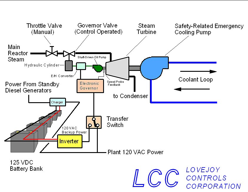
The US Nuclear Regulatory Commission (NRC) through the efforts of the Near-Term Task Force on the Fukushima Event has identified SBO mitigation as a major corrective action to harden operating nuclear power plants against greater than design basis environmental seismic, flooding, and terrorist attack. The NRC further recommends a "Defense in Depth" approach to mitigating such events.
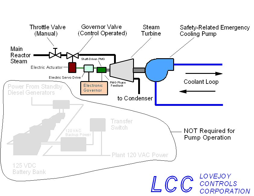
LCC has developed (Patent Pending) a new technology which in itself provides a high level of SBO mitigation at a practical investment cost. The new technology consists of a Variable Speed, Constant Output Permanent Magnet Generator (PMG) which may be coupled to nuclear safety related pump turbine drives and fully power the respective turbine digital controls, electric governor valve operators, and operator control station equipment independent of external power feeds. This design overcomes traditional PMG limitations to single generation speeds and allows full operation power feed from 500 to 5000 RPM of turbine speed.
Existing original designs and proposed digital upgrade system designs retain SBO vulnerability by requiring station AC electrical power or standby battery bank DC or inverted AC power to remain in control of the safety related steam turbine driven pumps. The SBO condition removes these electrical power sources either coincident with the damaging event or within a period of hours if the battery bank is undamaged. Plant specifications differ, but vital battery capacity ranges from less than eight hours to thirty-two hours at operating plants. Since reactor core cooling requirements extend for weeks, additional mitigating measures are necessary.
The placement of diesel powered portable pumps either on site or within short range transport having engineered water sources, suction line designs, discharge line designs, and fueling support represents one defense strategy. However, coincidental damage to the portable equipment by the SBO initiating event cannot be assumed absent in a practical risk assessment. Transport requirements for remote pump storage also depend upon secure storage, routine availability testing, and a functioning infrastructure for delivery. These are far too many assumptions to qualify standby portable pumps as a full corrective action.
Seismic re-qualifications to higher standards are also being examined for standby power feed equipment, conduit and cable runs which may prove costly to implement in operating plants.
While much has been discussed on the subject of SBO Mitigation, the LCC PMG represents a true corrective action solution.
The PMG self-powered system adds the key mitigation factor for a defense-in-depth corrective action by eliminating the need for any external electrical power feeds to the turbine controls and controlling instruments. The PMG may also be redundant, and controls may auction PMG power with external feeds with a final alignment based upon individual application risk analysis. The LCC PMG solution also has the following advantages:
Page designed and Copyrighted -Lovejoy Controls Corporation U.S.A 2025